Hacking a router 02: A first look
Overview
Now that we have everything to get started it’s time to take a closer look at the target.
This is what the inside of the router looks like:
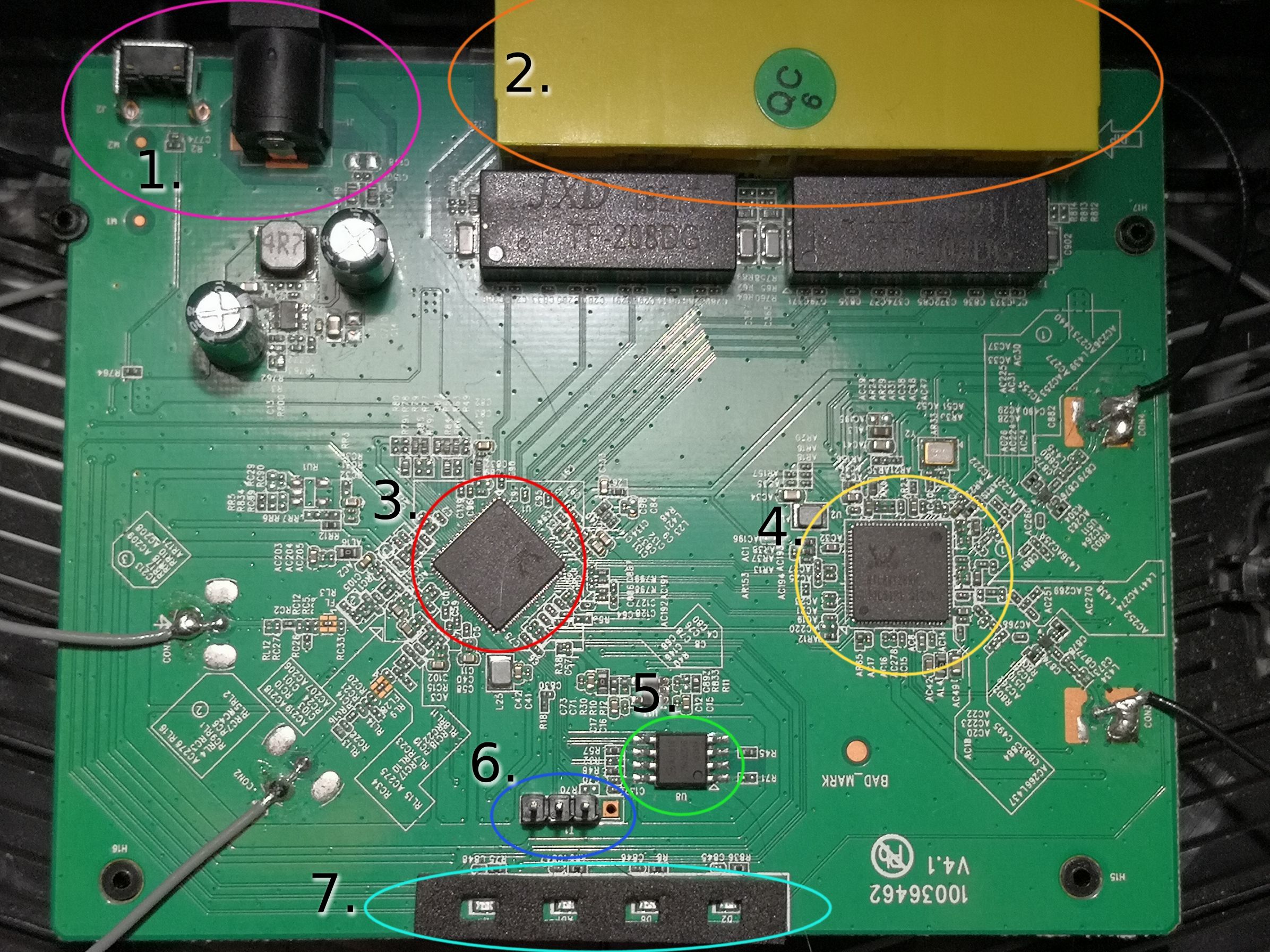
Hardware Summary
1. DC-IN and Reset/WPS button
2. 1 WAN port + 3 LAN ports
3. Main CPU (RTL8197FNT)
4. Network Controller (RTL8812BRH)
5. Flash Memory (gd25q16)
6. UART Serial Interface (GND, RX, TX)
7. 4 LEDs
Now that we know what’s on the PCB it’s time to get to know the parts in more detail.
Details
Let’s start with the CPU: it’s a RTL8197FNT which is a CPU of the MIPS32 architecture.
It has 32MB DDR2 RAM at 533MHz available.
The CPU architecture is one of the most important pieces of information to have and pretty much all we need for now.
Next up is the Network Controller: a RTL8812BRH. It is most likely used for the 2.4GHz and 5GHz wireless interfaces of the router.
And then we have the flash memory: gd25q16. It’s 2048K-Byte in size and contains the kernel and other data the device needs to operate.
Exploring UART
Now that we know what makes the router work we can start to figure out how to get in.
In general you first want to try the path of least resistance, which in this case clearly is the UART Interface (which did not have soldered headers btw).
To figure out the pin out you want to take your multimeter and put it into continuity mode. This will make your multimeter beep when there is a low resistance path between the two probes. With this we can figure out which the GND pin is by putting one probe onto ground (for example at the DC-IN jack) and the other on any of those 4 pins. If we get a beep then we found the ground connection.
If you notice there are 4 pads. Often times there is also one that is connected to VCC.
We can find that one by putting the multimeter into DC-Voltage mode and holding the probe that is plugged into the common terminal (usually the black one) on a ground connection and holding the other one on any of the pins.
If you get a steady reading (usually 3,3V or 5V) then you found it.
If it fluctuates it’s most likely one of the other two pins.
Now that we were able to identify 2 out of the 4 pads we know that we only have the transmit (TX) and receive (RX) connections left.
There are a few methods to identify those connections. You can either use a logic analyzer or oscilloscope or you can just try it.
But before you connect your USB-Serial converter you should check the voltage potential on it’s connections. Mine has a jumper to switch between 3.3V and 5V. It’s important to match those with your device, if you have a converter that only has 5V for example, you should build a voltage divider and bring the voltage to a compatible level.
At this point you’re ready to hook up your USB-Serial converter. Connect GND to GND, TX to what you think is RX and RX to what you think is TX (Yes you connect them to the opposite).
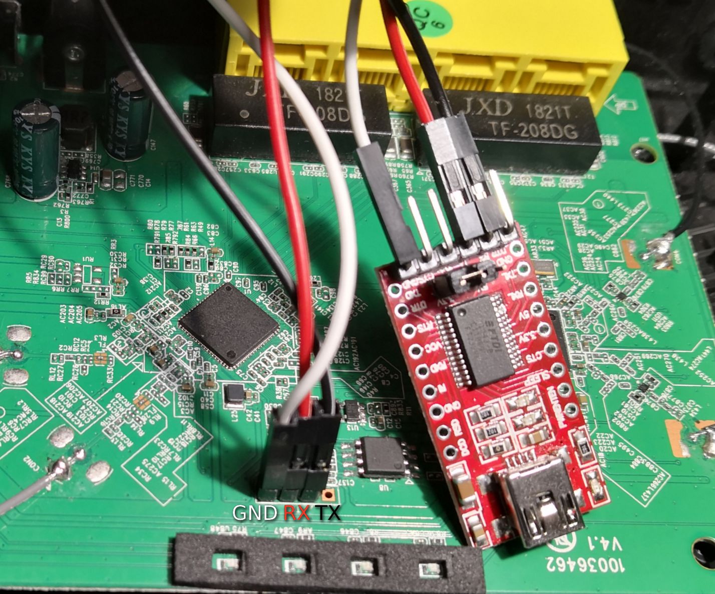
Then you start a terminal on your computer, I’m using picocom, and set the baudrate to one of the common ones (110, 300, 600, 1200, 2400, 4800, 9600, 14400, 19200, 38400, 57600, 115200, 128000 or 256000). Then connect your device and watch the terminal, if you get any output, even if it’s garbage, then you most likely have it hooked up correctly. If you don’t get anything try to swap the TX and RX connections.
This kind of output is caused by a mismatching baudrate. To get proper output we need to find the right baudrate, which is often one of the ones mentioned above.
In this case it’s 38400 and by setting that baudrate we get this output:
We’re going to explore the serial interface more in the next part.